Polar
Role
The Polar module assists with mount polar alignment. It acquires three sky images while moving the mount in RA between each shot, plate-solves each image, then computes the azimuth and altitude error of the polar axis. A continuous correction loop then guides the user while they mechanically adjust the mount.
Required devices
| Device | Role |
|---|---|
| Camera | Image acquisition for plate solving |
| Mount | RA movement and coordinate readout |
| GPS | Observer geographic position |
Parameters
| Parameter | Description |
|---|---|
| Exposure | Exposure duration in seconds |
| Gain | Camera gain |
| Offset | Camera offset |
| Focal length | Optical focal length in mm — used to define the solver image scale |
Algorithm
Phase 1 — Calibration (3 images)
The module acquires three images with a 30-minute (0.5 h) RA slew between each shot:
- Image 0 — initial position
- ±0.5 h RA slew (direction adapted to pier side)
- Image 1 — new position
- Another ±0.5 h RA slew
- Image 2 — final position
Each image is plate-solved. The three solutions (RA, DEC in J2000) are converted to horizontal coordinates (azimuth/altitude) at the exact time of each exposure, taking the observer’s geographic position into account.
Polar axis computation
The three Az/Alt points trace an arc on the celestial sphere corresponding to the mount’s rotation. The module computes the normal vector to this arc — this is the actual direction of the mount’s rotation axis.
Errors are then derived:
| Error | Definition |
|---|---|
| Azimuth error | Difference between the axis azimuth and North (azimuth = 0°) |
| Altitude error | Difference between the axis altitude and the observer’s latitude |
| Total error | Combined error: √(az² + alt²) |
Errors are displayed in degrees and arcminutes.
Phase 2 — Correction loop
After calibration, the module enters a continuous loop with no mount slewing:
- Acquire an image
- Plate-solve
- Compute the Az/Alt displacement relative to the reference image (image 2)
- Update the residual error = initial error − correction already applied
The user mechanically adjusts the mount’s azimuth and altitude; the residual error decreases in real time as alignment improves.
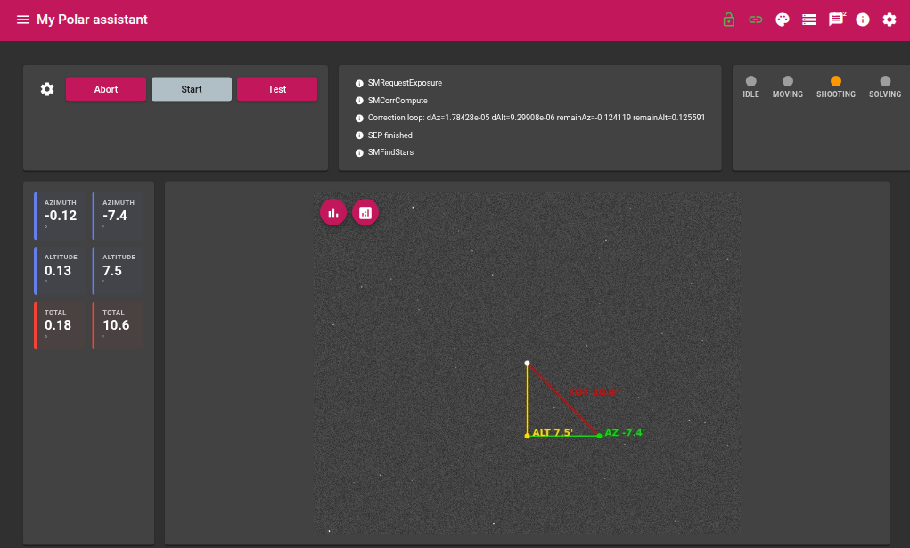
Graphical overlay
The displayed image includes an overlay showing the corrections to apply:
| Line | Colour | Meaning |
|---|---|---|
| Polar axis → altitude correction | Yellow | Altitude error |
| Altitude correction → pole | Green | Azimuth error |
| Polar axis → pole | Red | Total error |
The frame is oriented so that celestial North is at the top of the image.
States
| State | Description |
|---|---|
| Idle | Module inactive |
| Moving | Mount slewing |
| Shooting | Image acquisition in progress |
| Solving | Plate solving in progress |
| Compute | Polar error computation |
Live values
Calibration measurements
| Value | Description |
|---|---|
| RA 0 / DE 0 / Time 0 | Astrometric solution and timestamp for image 0 |
| RA 1 / DE 1 / Time 1 | Astrometric solution and timestamp for image 1 |
| RA 2 / DE 2 / Time 2 | Astrometric solution and timestamp for image 2 |
Polar error
| Value | Description |
|---|---|
| Azimuth error (°) | Azimuth error in degrees |
| Altitude error (°) | Altitude error in degrees |
| Total error (°) | Combined error in degrees |
| Azimuth error (arcmin) | Azimuth error in arcminutes |
| Altitude error (arcmin) | Altitude error in arcminutes |
| Total error (arcmin) | Combined error in arcminutes |
Actions
| Action | Description |
|---|---|
| Start | Starts the calibration sequence (3 images + computation) then enters the correction loop |
| Abort | Immediately stops the current sequence |