Guider
Role
The Guider module provides automatic telescope guiding. It acquires a reference star field, measures the field drift in real time and sends timed correction pulses to the mount to hold the pointing.
Required devices
| Device | Role |
|---|---|
| Guide camera | Image acquisition for the guide field |
| Guide interface | Receives the timed pulses (TELESCOPE_TIMED_GUIDE_*) — the mount itself, or a device relaying ST4 pulses |
Operating phases
Guiding runs through three sequential phases.
Phase 1 — Initialization
The module acquires a reference image and keeps the detected star list as the reference for the whole guiding session. When guiding is started with a valid stored calibration, only this phase runs before guiding; a fresh reference is taken at the current pointing, so calibration can be reused after a slew.
Phase 2 — Calibration
The module measures the mount’s response to correction pulses.
- A fixed series of pulses is sent West, then East, then North, then South (
Calibration stepspulses per direction). - The per-pulse image displacement of each pass is measured against the previous frame.
- The pulse rate is taken from the antisymmetric combinations
(West − East) / 2and(North − South) / 2. A one-directional pass is contaminated by the constant background drift (sidereal tracking error, periodic error, polar-alignment drift); the difference of the two opposite passes cancels that drift and yields one clean RA rate and one clean DEC rate. The raw per-direction rates are still reported, for diagnostics. - The CCD orientation is derived from both axes (an RA-axis and a DEC-axis estimate, averaged), with the 180° ambiguity resolved against the RA axis.
- The RA rate is normalised to the equator (
rate × cos(calibration DEC)) so it can be transferred to any declination at guide time.
Before the North and before the South series, an optional DEC backlash kick pulse takes up the DEC axis’ mechanical play first, so the timed measurement pulses aren’t partly wasted re-engaging the gears. Its own movement is excluded from the rate calculation.
The calibration result is saved and reused across sessions, as long as the pier side and camera orientation have not changed.
After the four passes the module reports a drift ratio — how large the constant background drift was relative to the pulse displacement — and a Calibration quality light (green / orange / red). If the ratio exceeds Max background drift ratio, the calibration is rejected and restarted, up to Calibration retries times, then aborted with a “check polar alignment” message. A calibration is also aborted if the star drifts further than Max star excursion from its starting position, before it can leave the sensor.
Phase 3 — Guiding
Continuous correction loop:
- Acquire an image.
- Track the star field against the reference (see Star tracking below).
- Compute the drift, projected onto the RA and DEC axes with the calibration orientation.
- PI control — the correction is
aggressivity × drift + integral gain × accumulated drift. The proportional term alone cannot null a constant drift (it settles atdrift / aggressivity); the integral term keeps building until the residual is actually zero. The accumulator is clamped (Integral clamp) and frozen for an axis whose pulse is already at maximum. - The RA rate is scaled for the current declination:
equatorial rate / cos(current DEC). - If DEC backlash compensation is enabled and the DEC direction reversed since the last correction, the current compensation estimate is added on top.
- Correction pulses are sent to the mount, clamped to Min pulse / Max pulse.
- Statistics are updated (RMS RA, DEC, total).
- If a compensated reversal pulse was sent on the previous cycle, the drift reduction it actually achieved is compared with the prediction and the compensation estimate is nudged up (undershoot) or down (overshoot), within the configured bounds.
The first frame of a session is measured but not corrected — it only sets the working zero, so a few pixels of post-slew settle don’t trigger a large first pulse.
A transient loss of star correlation just skips the frame (no pulse); guiding is aborted only after Max consecutive lost frames in a row. A hardware watchdog aborts the session if an exposure, pulse, frame reset or star extraction never completes within Hardware timeout.
Mount gears have mechanical play: whenever DEC guiding reverses direction, the first pulses partly take up that play instead of producing real movement, causing a temporary drift spike. The true backlash amount varies with pointing position and load, so a fixed value tends to under- or over-correct. The adaptive estimate self-tunes: each reversal is both a correction and a measurement, so it converges toward whatever backlash currently exists.
Star tracking
Between two frames the star field undergoes a near-pure translation (a meridian flip’s 180° rotation is handled separately by the reverse flags). Tracking looks directly for the dominant translation:
- Every (reference star, current star) pair implies a candidate translation; the true one is the translation the most stars agree on (a voting / RANSAC step).
- Its inliers are refined with a two-stage gate and iterative sigma-clipping, and the drift is a flux-weighted mean of the residuals — continuous and sub-pixel.
This is immune to a change in the stars’ flux ranking and to stars appearing or disappearing between frames. The relevant tuning is under Star matching in the parameters.
A pulse moves the star by rate × pulse × cos(DEC) on the sensor, so ms/px scales as 1 / cos(DEC). The RA rate is therefore stored normalised to the equator at calibration time and divided by cos(current DEC) when guiding, so a calibration done at one declination stays correct at another.
Parameters
Parameters are reached from the module Parameters menu and a set can be saved as a profile.
Devices
| Parameter | Description |
|---|---|
| Exposure | Exposure duration in seconds |
| Gain | Camera gain |
| Offset | Camera offset |
Calibration
| Parameter | Description |
|---|---|
| Pulse duration | Duration in ms of each calibration pulse |
| Calibration steps | Number of pulses per direction |
| DEC backlash kick | Extra pulse (ms) before the North and the South series, to take up mechanical play first — 0 disables it |
| Max background drift ratio | Reject the calibration if the constant background drift exceeds this fraction of the pulse displacement — a high value usually means poor polar alignment. 0 disables the check |
| Calibration retries | How many times to restart a rejected calibration before giving up |
| Max star excursion | Abort calibration if the star drifts further than this fraction of the smaller frame dimension from its start. 0 disables |
Guiding
| Parameter | Description |
|---|---|
| Max pulse | Maximum correction pulse duration (ms) |
| Min pulse | Minimum correction pulse duration (ms) |
| RA aggressivity | Proportional fraction of the computed RA correction applied |
| DEC aggressivity | Proportional fraction of the computed DEC correction applied |
| RA integral gain | Gain on the accumulated RA residual — nulls the steady-state lag against a constant drift. 0 = pure proportional |
| DEC integral gain | Same, for the DEC axis |
| Integral clamp (px) | Anti-windup: magnitude the integral accumulator is clamped to. 0 disables the clamp |
| RMS threshold | Multiplier of the current RMS beyond which a correction is discarded |
| RMS drift over x | Number of frames the RMS is computed over |
| Enable pier side reverse | Automatically reverse the RA/DEC corrections when the pier side differs from calibration |
| Dither amplitude (px) | Maximum random offset applied on a dither |
| Max consecutive lost frames | Skip a guide frame on lost star correlation; abort only after this many in a row |
| Hardware timeout (s) | Abort if the camera or mount stops responding for this long. 0 disables the watchdog |
Star matching
| Parameter | Description |
|---|---|
| Star match gate (px) | Search radius when matching a reference star to the current frame |
| Min matched stars | Fewest reference stars that must be recovered for the drift to be trusted |
| Max stars used | Cap on the brightest stars taken from each frame |
DEC backlash compensation
| Parameter | Description |
|---|---|
| Enable | Add an adaptive extra pulse whenever the DEC guide direction reverses |
| Current compensation (ms) | Adaptive estimate, adjusted after each reversal — set an initial guess or leave at 0 and let it learn |
| Minimum / Maximum compensation (ms) | Bounds for the adaptive estimate |
| Adjustment step (ms) | How much the estimate is nudged after each reversal, based on measured over/undershoot |
Manual reversals
| Parameter | Description |
|---|---|
| Reverse RA | Manually reverse the RA correction direction |
| Reverse DEC | Manually reverse the DEC correction direction |
Disable corrections
| Parameter | Description |
|---|---|
| Disable RA+ / RA− / DEC+ / DEC− | Disable correction pulses in that direction |
Test aids
| Parameter | Description |
|---|---|
| SIM: fake meridian flip | Adds 180° to the calibration angle at guide start (the effect a real flip has on the drift → RA/DEC mapping), so reverse-correction handling can be exercised against the CCD Simulator, which never rotates its own field. Leave OFF in real use |
Calibration values
| Value | Description |
|---|---|
| Calibration quality | Light: green (clean) / orange (usable, significant background drift) / red (rejected) |
| RA rate (ms/px) | Equatorial RA rate used for guiding (West/East combined, drift removed) |
| DEC rate (ms/px) | DEC rate used for guiding (North/South combined) |
| raw N / S / E / W (ms/px) | Raw per-direction rates, diagnostic only (still carry the background drift) |
| CCD Orientation | Calibration angle (degrees) |
| Calibration Mount DEC | Mount declination at calibration time |
| Reverse RA / DEC | Correction reversals stored at calibration time |
Live values
| Value | Description |
|---|---|
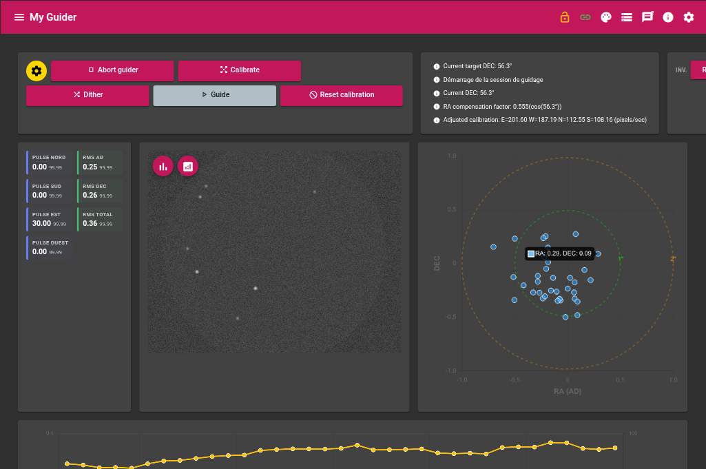
| Pulse N / S / E / W | Duration of the last pulse in each direction (ms) |
| RMS RA / DEC / total | Root-mean-square of the drift (pixels) |
Graphs
Drift (scatter)
XY scatter of the drift of each correction relative to the reference position, with tolerance rings.
Guiding (time series)
PHD2-style graph showing, per correction:
| Curve | Description |
|---|---|
| RA drift / DEC drift | Measured drift on each axis (pixels) |
| RA pulse / DEC pulse | Correction pulse duration (ms) |
| SNR | Signal-to-noise ratio of the star detection |
| RMS | Current total RMS (pixels) |
Actions
| Action | Description |
|---|---|
| Calibrate | Initialization then calibration only |
| Guide | Start guiding — uses the stored calibration, or calibrates first if there is none |
| Abort | Immediately stop the current sequence |
| Reset calibration | Clear the saved calibration data |
| Dither | Randomly offset the guiding position by up to Dither amplitude |